Copyright © 1995-2000 MZA Associates Corporation
tve Reference Manual
tempus visual editor
Introduction
Installation and Setup
Starting the tve
tve Main Window
System Editor
Runset Editor
Troubleshooting
The tempus visual editor (tve) is a graphical user interface (GUI) which facilitates the creation, editing, and execution of simulations using tempus. The purpose of this manual is to provide a comprehensive reference of all tve functions. To find information about a particular function, use the Contents section to navigate to the section of general interest. From that section, use the graphical links to get to more specific information.
This manual is not intended as a tutorial for building and executing tempus systems. That information can be found in the tempus Simulation User's Guide and in various other tempus and WaveTrain tutorial documents.
The tempus Visual editor (tve) is a graphical user interface (GUI) program which facilitates the definition and construction of tempus composite systems. Constructing composite systems consists of organizing simple systems and connecting their inputs and outputs so that, taken together, they provide the desired functionality. Once a composite system is constructed, the user may then specify the value of the system's parameters to provide the basic inputs and to provide run-specific functionality.
Interactions with the user allow the specification of composite systems which can then be included in other composite systems. These composite systems are stored so they can be reused in later sessions. The primary output of the tve is the source code for the composite systems, which when compiled and linked with the tempus library, result in an executable program that provides the desired functionality. The tve also provides mechanisms to generate template source code for simple systems to be implemented by a programmer and generates template HTML documentation to assist in the process of documenting tempus Systems. The tve is implemented in the Java programming language.
Under normal circumstances the tve is properly installed by the InstallShield system which is provided with the tempus distribution materials. But sometimes the installation can be corrupted or the user will want to switch between versions and such. With this in mind, this section provides the information necessary to run the tve on most Windows-based systems.
Windows Environment
...
The tve is started by the execution of the tempus.bat, or for WaveTrain users wt.bat, file. Normally, these files are in directories which have been placed in the Windows PATH variable and a shortcut is installed under the Windows Start Menu Programs group. You can also install a link to the .bat files on your desktop and/or include them in your Quick Launch toolbar. Once you have started the tve, the Main Window will appear.
The following subsections describe the methods used to start the tve:
Starting the tve from the Windows Start Menu
Click on the Start Menu. Navigate to the program group which contains the
item with the ![]() or
or ![]() icon.
This item is usually named tve, tempus, or WaveTrain. Select the icon by clicking
on it. By default, the tempus or WaveTrain item is installed under the Programs
heading of the Start Menu.
icon.
This item is usually named tve, tempus, or WaveTrain. Select the icon by clicking
on it. By default, the tempus or WaveTrain item is installed under the Programs
heading of the Start Menu.
Starting the tve from a DOS or Command Line Window
Start a DOS or Command Line window using the Windows Start Menu. In that Window, type the following commands:
WaveTrain users:
C> setupwt
C> wt
Non-WaveTrain users:
C> setuptempus
C> tve
Starting the tve from a Shortcut installed on your
Desktop
If the tve is installed in your Desktop, the ![]() or
or ![]() icon
will appear next to the other Desktop icons. The tve will begin once you
double-click on the icon.
icon
will appear next to the other Desktop icons. The tve will begin once you
double-click on the icon.
Starting the tve from the Quick Launch Toolbar
If the tve is installed in your Quick Launch toolbar, the ![]() or
or ![]() icon
will appear. The tve will begin once you click on the icon.
icon
will appear. The tve will begin once you click on the icon.
When the tve is started, the tve Main Window pictured above is started. To navigate to more specific help information, click on one of the buttons. The Main Window stays open the entire time the tve is running. The user should place it on an out-of-the-way corner of his desktop or iconify it. From this Window, the user can:
click on Systems to start a System Editor
click on Run Sets to start a Runset Editor
click on Help to start a web browser containing tempus help information
click on Quit to close all tve windows and halt execution
Accompanying the main tve Window is an iconified Command Line window which serves as a console for the tve Java application. Users can normally ignore this window, but occasionally it is useful for troubleshooting problems.
The system editor is used to construct and edit composite tempus systems. It can also be used to create template code for simple tempus systems. A blank system editor is pictured above. In this state, one can only perform operations having to do with starting a new system or loading an existing system.
Overview of the System Editor
In the system editor subsystems are represented as icons connected through their inputs and outputs. Simple systems are those systems which do not contain any subsystems. Composite systems contain other composite systems and/or simple systems. With the system editor, the user creates a hierarchy which consists of nested subsystems with inputs, outputs, and parameters flowed down to the lowest level of simple systems. The top-level system contains all other systems and is used to encapsulate the functionality of the entire configuration.
The system editor is used for the following functions:
Construct
composite systems out of simple systems and other composite systems.
Edit composite systems to modify their behavior.
Specify subsystem parameter values to enable
run-specific behavior.
Generate template source code which is then used as a
starting point for coding a simple system.
Generate template HTML code which is then used as a starting
point for documenting a system.
Traversing Systems in the System Editor
The system editor represents hierarchical Systems which
are viewed in a nested fashion. To view the internal contents of a subsystem
contained within the currently viewed composite system (i.e., traverse down into
the subsystem), double-click on the subsystem Icon with the left mouse button. If
you traverse down into a subsystem which contains only external inputs and
outputs (i.e., there are no subsystems), then you have traversed into a simple
system. To view the internal contents of the composite system which
contains the currently viewed system (i.e., traverse up), double-click on white
space with the left mouse button or just single-click on the ![]() button located on the toolbar. Attempting to traverse upwards from the top-level
system will have no effect.
button located on the toolbar. Attempting to traverse upwards from the top-level
system will have no effect.
Elements of the System Editor
The system editor provides a graphical representation of a system by displaying and allowing the manipulation of a variety of graphical elements including subsystem icons, subsystem parameters, subsystem inputs and outputs, external inputs and outputs, and connections. The system editor provides numerous functions through the system editor menus and the system editor toolbar.
Below is an example of a System Editor with a loaded system. Click on one of the graphical items to navigate to more specific documentation.
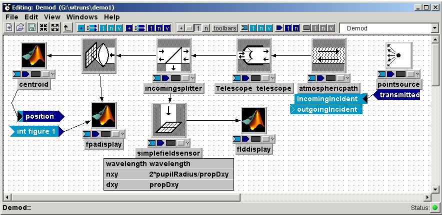
Subsystem icons are rectangular boxes which represent a given subsystem. These can be added to a block diagram, moved, copied, pasted, deleted, and replaced. Their appearance can be modified in various ways. By double-clicking on the icons, the user can traverse "down into" the subsystem to view its contents. Various graphical items may be attached to these icons to display additional information.
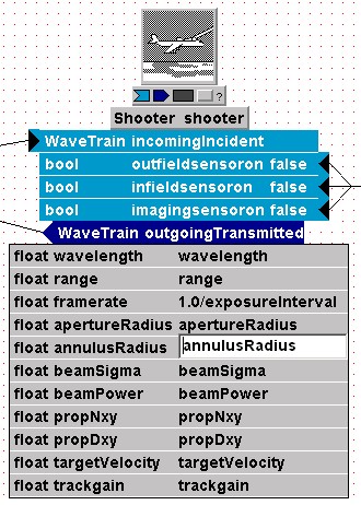
The first icon below shows a subsystem in its most spartan state. The second icon is shown with its toolbar, system name, and parameters. The last icon is shown with its toolbar, system type and name, inputs, and outputs. Using various buttons on the GUI, the user may display any combination of these items.

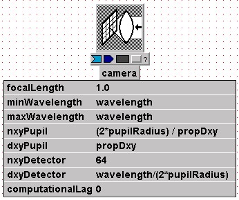
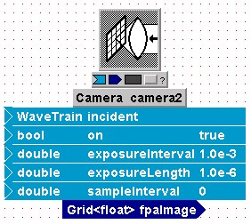
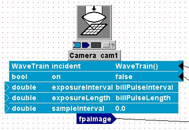
Two subsystem icons with parameters displayed are shown below. In the first, only the parameter names and values are shown. In the second, the parameter types are also displayed along with the subsystem inputs and outputs. In the second image, the user is in the process of editing the value of the parameter named annulusRadius.
Subsystem inputs and outputs are displayed as graphical tabs attached to the bottom of subsystem icons. These represent the dynamic inputs and outputs of the attached subsystem. Inputs are light blue, have an arrow-shaped input-port, and may be connected to an output of a subsystem or an external input of the currently viewed composite system. Outputs are dark blue, have an arrow-shaped tip, and may be connected to the input of a subsystem or an external output of the currently viewed composite system.
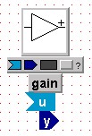
The first image below is an example of a subsystem icon shown with its input and output. In this case only the names of the input and output are shown and neither is connected. In the second image, one input is connected and one output is connected. The type names for both inputs and outputs are also shown. The filled-in input port indicates that the associated input has a default value and does not need to be connected. In the third image, the inputs' setting expressions are shown. In this case, the user has entered an expression that will be used to calculate the value of the input during runtime should it remain unconnected.
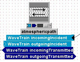
External inputs and outputs are displayed as graphical tabs which represent the inputs and outputs of the currently viewed composite system. Unlike the subsystem inputs and outputs, these tabs are always displayed and are not attached to icons. External inputs have an arrow-shaped tip and may be connected to any number of subsystem inputs or external outputs. The external output has an arrow-shaped input port and may be connected to subsystem output or an external input.
Two external inputs and four external outputs are shown below. These tabs can be shown in various states, including with and without their types, names, and default values. Unconnected external outputs with filled-in input ports have default values which will be used as long as it is not connected. The default values specified for external inputs are used when its corresponding input is not connected in the containing system.
Connections are arrow-tipped lines drawn between external inputs and outputs, subsystem icons, and subsystem inputs and outputs. These lines represent input-output relationships between the edited system's containing system and its subsystems. The Connection lines are usually drawn directly to the connected input or output if it is displayed. When the inputs or outputs of a connected subsystem are not displayed, then the connection lines are drawn directly to the subsystem icon. By clicking on the connection line and stretching it, the user can create vertices which help to route the connection around other graphical objects. These vertices can be removed by clicking on them with the third mouse button. The image below shows connections displayed in a variety of ways.
System Editor Menus
The system editor menus provide numerous functions for creating and editing tempus systems. Click on the menu heading below to navigate to more specific information.
![]()
System Editor File Menu
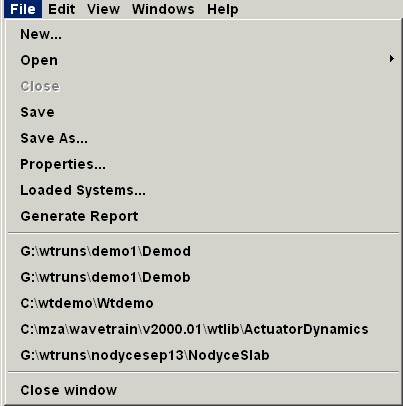
The File Menu provides numerous options for creating, loading, and saving tempus Systems. Click on a menu item below to navigate to more specific information.
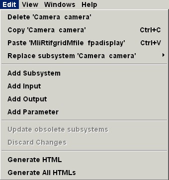
System Editor Edit Menu
The Edit Menu provides numerous options for modifying the block diagram through standard GUI editing functions. Click on a menu item below to navigate to more specific information.
System Editor View Menu
The View Menu allows various features of the GUI to be displayed or hidden. Click on a menu item below to navigate to more specific information.

System Editor Windows Menu
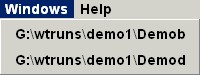
The Windows Menu allows the user to specify which of the currently loaded systems should be displayed in the window. When the Windows tab is selected, a list of the currently available top-level systems is displayed, with the currently displayed system always listed first. The user should then select the system that he wishes to be displayed. In the example below, the user is shown two systems which he can select.
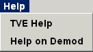
System Editor Help Menu
The Help Menu gives the user access to documentation. Selecting "TVE Help" will cause a web browser to be launched displaying general tempus documentation. The second option, "Help on..." will display the documentation available for the currently displayed system.
File![]() Open
Open
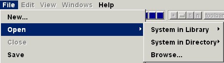
Using File![]() Open
the user may load a tempus system into
the System Editor. With the three options, the user can load a system from a
previously accessed library or regular directory, or browse the entire
accessible file space. In any case, the tve displays a file browser dialog
(below) which the user uses to select the .tsd file of the System he wishes to
load. The file browser does not allow users to access network drives unless they
have been mapped to a drive letter.
Open
the user may load a tempus system into
the System Editor. With the three options, the user can load a system from a
previously accessed library or regular directory, or browse the entire
accessible file space. In any case, the tve displays a file browser dialog
(below) which the user uses to select the .tsd file of the System he wishes to
load. The file browser does not allow users to access network drives unless they
have been mapped to a drive letter.
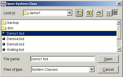
To navigate upwards in the directory structure, the user
employs the "Look in:' drop down list or the ![]() button. To enter subdirectories shown in the the user either double-clicks
on a subdirectory or single-clicks and presses Open. Once the desired .tsd file
is found, the user double-clicks it or single-clicks and presses Open. The load
operation can be cancelled by clicking the Cancel button.
button. To enter subdirectories shown in the the user either double-clicks
on a subdirectory or single-clicks and presses Open. Once the desired .tsd file
is found, the user double-clicks it or single-clicks and presses Open. The load
operation can be cancelled by clicking the Cancel button.
